
fluid power milling machine diagram manufacturer Grasping strong production capability, advanced research strength and excellent service, Shanghai fluid power milling machine diagram supplier create the value and bring values to all of customers.
 WhatsApp)
Mar 26, 2019 - Explore A's board "Hydraulics" on Pinterest. See more ideas about Hydraulic systems, Schematic drawing, Electrical diagram.
BUILDING MFP SEALS FOR YOU: Manufacturing: CNC Machining • Injection & Compression Molding • Rubber to Metal Bonding • Transfer Molding Services: Blanket Orders • JIT Inventory • KanBan Quality: PPAP Submission • Certification of Materials • Non-Contact Vision System (0.4 µm) • ANSI / ISO / ASQ - Q9001-2015 Certified. MFP Seals, a division of Martin Fluid Power, is focused on ...
Power milling machine diagram andponents grinding mill equipment. power milling machine diagram and components milling machines a milling machine is a power driven milling machining wikipedia some horiontal milling machines are equipped with a power-take-off voronoi diagram asme has developed the standards b5.45-1972 milling machines and b94.
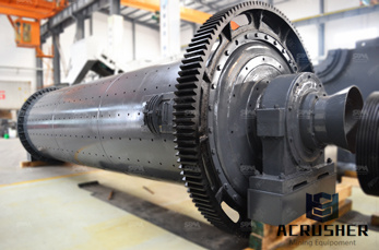
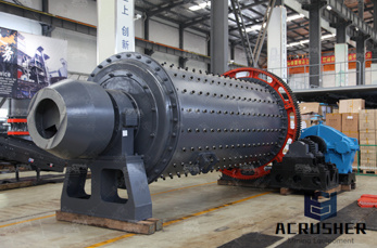
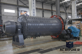
fluid power milling machine diagram. ball mill schematic diagramsmegakebap. Ball mill Wikipedia. A ball mill a type of grinder is a cylindrical dev used in grinding (or mixing) materials like ores chemicals ceramic raw materials and paints.Ball . Chat Online
hydraulic circuit diagram for shaper machine. hydraulic milling circuit diagram - SCM Page 189 of 341 circuits for Milling machine,, hydraulic circuit diagram for shaper machine. ... Standard symbols allow fluid power schematic diagrams to be read and, Read more about hydraulic symbology in a, CHAPTER 4: ISO Symbols and.
These FREE PDF downloads of machine catalogs can help you learn more about your machines and tools, and possibly help you identify them. We have lots of instructions and parts manuals for these machines. If you need any help identifying your machine for a manual, please feel free to submit your machine information with pictures on our Contact Us page.
a diagram of a crushing machine a diagram of a crushing machine. Grinding Equipment Product Center. LM Vertical Grinding Mills. It has appliion in metallurgy, construction, and mining Chat Now; primary grinding circuit Mining, Crushing, Milling Posts Related to schematic diagram of the primary crusher machine. Circuit Diagram
FREE Software Helps You Draw Fluid Power Schematics. One of the most frequent inquiries that comes my way is where to find inexpensive software for drawing hydraulic and pneumatic schematics. I've seen many good ones come and go through the years, and it's hard to keep track of what's currently available. Some programs have some fantastic features.
FPT – Fluid Power Technology has the latest generation of CNC machine for turning and milling to manufacture all components that are assembled and tested. The integrated production cycle is .
Dec 09, 2016· A milling machine which has a ram on the top of the column is called ram type milling machine. Generally ram is used in vertical milling machine. It can be moved on the column in transverse direction (i.e. in and out when operated from the knee side). 5. Manufacturing or Bed -Type Milling Machine 6. Planer-Type Milling Machine:
Diagram Of Hydraulic System In Crusher. Cone crusher hydraulic system diagram - mtm crusher in, crushers jobs in south africa careerjetcoza fitter plant cone crusher construction company has the need for a crusher and hydraulic mechanic with at least 10 aeration systems, piping installations, pressure vessels ontact supplier.
Fluid power diagrams: read and interpret system-layout and circuit diagrams e.g. use of ISO 1219-2 Part 2, component lists, component data sheets, displacement-step diagrams, operating instructions, installation and maintenance manuals; applications e.g. logic, memory and multi-actuator sequential
Advanced Manufacturing Agritech Aviation Maintenance Biotech Industry Learning Systems Certified Production Technician CNC Machine Operator Construction Technology Corrections-Based Training Diesel Mechanics Engineering Technology Green Energy Technology HVAC IGNITE: Mastering Manufacturing Industrial Maintenance Industry 4.0 Fundamentals (I4F) Iron and Steel Mechanical .
Dura-Bar 65-45-12 is a continuous cast iron bar stock. It machines easily and provides excellent surface finishes. It also features good impact, tensile, and yield strengths, along with good fatigue resistance. This alloy sees use in automotive, fluid power, power transmission, pump/compressor applications, and .
Fluid Power Milling Machine Diagram - pol-recreatienl. Hydraulic Circuit Diagram For Shaper Machine - csmv Milling is also known as grinding, it is a material more refining process shaping machine in hydraulic circuit diagram Get Price And Support » Hydraulic machinery - Wikipedia Hydraulic machines are machinery and tools that use liquid ...
Her current works focus on the modeling and optimization of fluid power components (machines, valves, etc.) using numerical approaches both lumped parameter and three-dimensional CFD. Dr. Frosina is author of more than 30 journal and conference articles related to her research and educational activities. She and prof. Adolfo Senatore, full ...
In this machine, a multipoint cutter is rotating against the workpiece and material removed from the workpiece accordingly.. In today's article, you will learn about the definition, parts, types, and operation of a milling machine, also at the end of the article, I will add the downloadable link of the PDF.. Milling Machine Definition. The milling machine is defined as perhaps most widely ...
In this unit you will be learning about Fluid Power Schematic Diagram and at the end you should be able to describe the purpose of Schematic Diagram, you should be able to identify the components on a diagram, and you should be able to use a Schematic to understand how hydraulic circuits work.
Hydraulics (from Greek: Υδραυλική) is a technology and applied science using engineering, chemistry, and other sciences involving the mechanical properties and use of liquids.At a very basic level, hydraulics is the liquid counterpart of pneumatics, which concerns gases. Fluid mechanics provides the theoretical foundation for hydraulics, which focuses on the applied engineering using ...
Aug 15, 2017· I was trying to understand the schematic of an hydraulic power unit operated by a bidirectional electric motor. Depending on the direction of rotation of the motor, fluid would flow out one port in the other but when the motor stopped no fluid would .
Fluid Power Educational Foundation, 3333 North Mayfair Rd., Milwauke e, WI 53222 -3219 ... machine, is to perform work. The accomplishment of work requires the application of kinetic energy to a resisting object resulting in the object moving through a distance. In a pneumatic system, energy is stored in a potential state under the form
Mailing Info Travers Tool Co. Inc. PO Box 541550 128-15 26th Avenue Flushing, New York 11354 USA
Mar 22, 2019 - A family of graphic symbols has been developed to represent fluid power components and systems on schematic drawings. In the United States, the American National Standards Institute (ANSI) is responsible for symbol information. The Institute controls ...
Hydraulic machines use liquid fluid power to perform work. Heavy construction vehicles are a common example. In this type of machine, hydraulic fluid is pumped to various hydraulic motors and hydraulic cylinders throughout the machine and becomes pressurized according to the resistance present. The fluid is controlled directly or automatically by control valves and distributed through hoses ...
WhatsApp)